
|
Arduino Project: Oskar van Deventer's 4-Bit Maze |
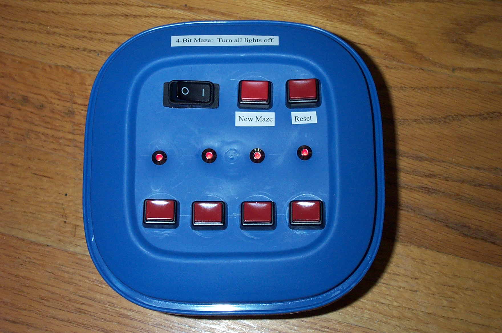
The implementation of Oskar van Deventer's 4-Bit Maze is an excellent beginner Arduino project that makes simple use of pushbutton switches and LEDs for digital input and output, respectively. The 4-bit maze, as the name implies, is a maze with a state encoded as four binary bits and displayed as on/off LEDs. Initially, all four lights are on (i.e. the initial state is 11112=1510). The object is to turn all four lights off (i.e. the goal state is 00002=010). In each state, each "on" bit may be selected. Each leads to a different state with that bit "off", yet other bits may change as well. This is better experienced than described, so try playing with the following 4-bit maze applet:
This applet features four buttons, each depicting an on/off state with a light bulb image. Clicking a button that is "on" has the effect of turning that button off, but may cause other buttons to turn on/off. In addition to clicking the buttons, you may also click the background next to the buttons to focus key presses to the applet. Then, you may press keys "1", "2", "3", and "4" to more easily press the buttons. "Reset" will reset you to the initial state where all lights are on. "New Maze" will generate a new maze and reset to the initial state.
Download the Arduino sketch FourBitMaze.pde. The sketch initially generates the same random four-bit maze each time (seed 42). Thereafter, the random maze generation is seeded with millis() (i.e. the current time in milliseconds) at the time a new maze is requested. Arduino digital input pins 2-5 reads buttons corresponding to state bits 0-3 (numbered right-to-left). Digital input pin 6 reads a "Reset" button that resets to the initial state with the same maze. Digital input pin 7 reads a "New Maze" button that generates a new maze and resets to the initial state. Digital output pins 8-11 light LEDs corresponding to state bits 0-3. Thus a total of 10 digital pins are used.
No modification is necessary for the sketch to work. The "#define VERBOSE true" line directs the program to transmit status information to the Serial output. (This is handy for debugging your circuit. If this is not desired, change "true" to "false".) For example, examine this sample transcript of Arduino FourBitMaze Serial output. Assuming the same code, seed (42), and random number generation, the first maze will always be output as follows:
0(0): -1 -1 -1 -1
1(12): 2 -1 -1 -1
2(11): -1 9 -1 -1
3(5): 10 5 -1 -1
4(8): -1 -1 11 -1
5(6): 6 -1 3 -1
6(9): -1 4 8 -1
7(1): 8 0 10 -1
8(10): -1 -1 -1 6
9(10): 8 -1 -1 6
10(4): -1 13 -1 3
11(7): 12 9 -1 4
12(6): -1 -1 3 2
13(3): 14 -1 1 5
14(2): -1 13 2 7
15(9): 6 4 9 2
Each line is of the form: <state>(<minimum distance to goal>): <next state from bit 0> <next state from bit 1> <next state from bit 2> <next state from bit 3>
When there is no transition, this is represented by -1 ("NULL").
The maze may be (messily) represented by the following graph, which indicates the shortest solution sequence of button presses (bits 1, 2, 0, 2, 0, 1, 0, 3, 1) in bold arrows.
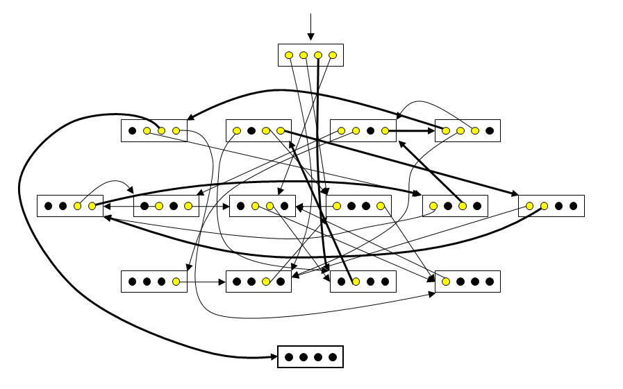
Note that this sequence is also followed in the transcript after it is reset.
Building the supporting circuit for the sketch is very easy. Essentially, we need to read 6 pushbuttons switches (bits 0-3, Reset, New Maze) and set 4 LEDs (bits 0-3). The building blocks for turning LEDs on/off and reading buttons are from the Loop and Button Arduino tutorials. The schematics for each LED and button portion of the circuit is as follows:
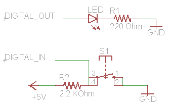
Note that there will be 6 DIGITAL_IN portions for Arduino input pins 2-7. and 4 DIGITAL_OUT portions for Arduino output pins 8-11. Thus, here is the necessary parts list:
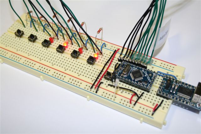
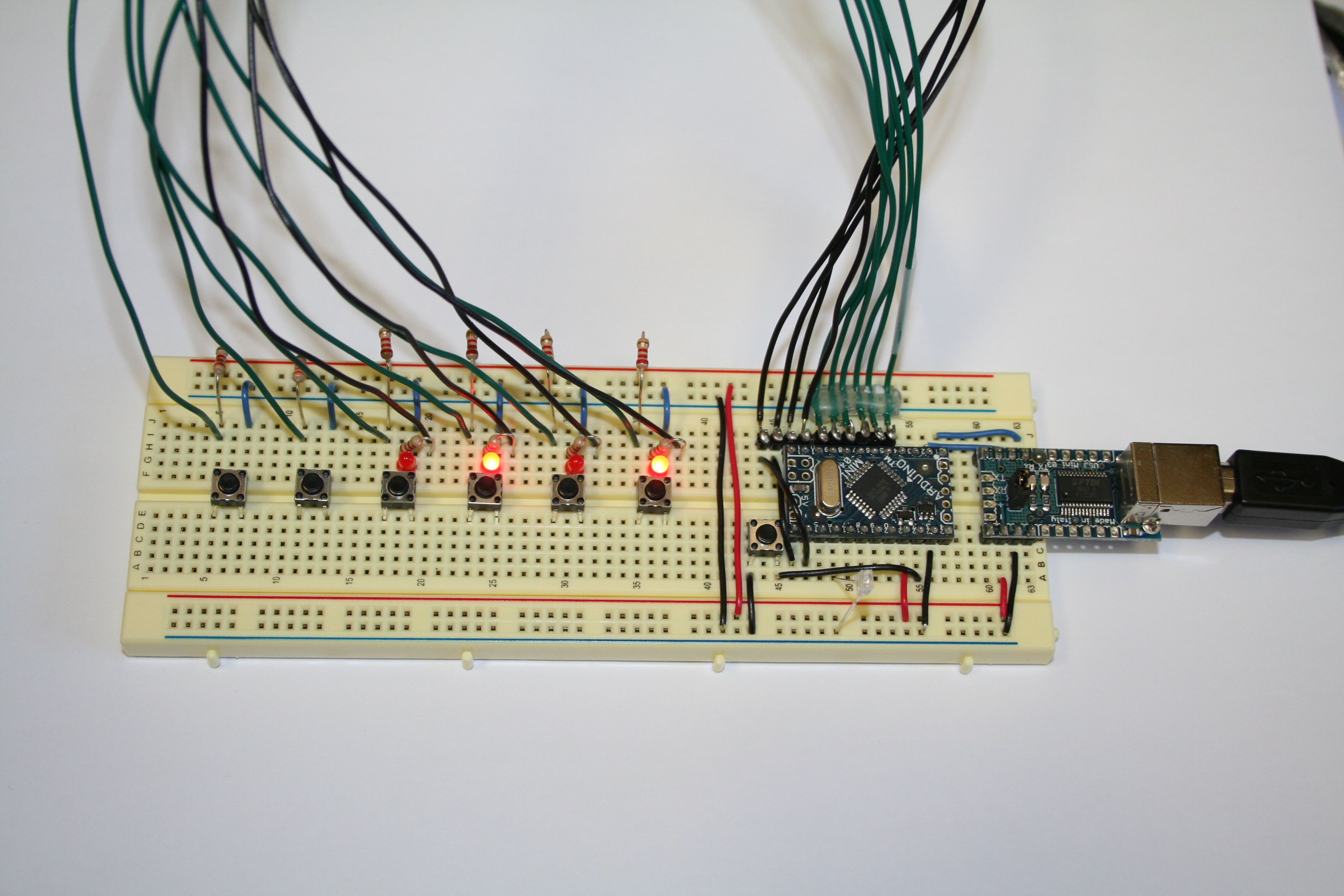
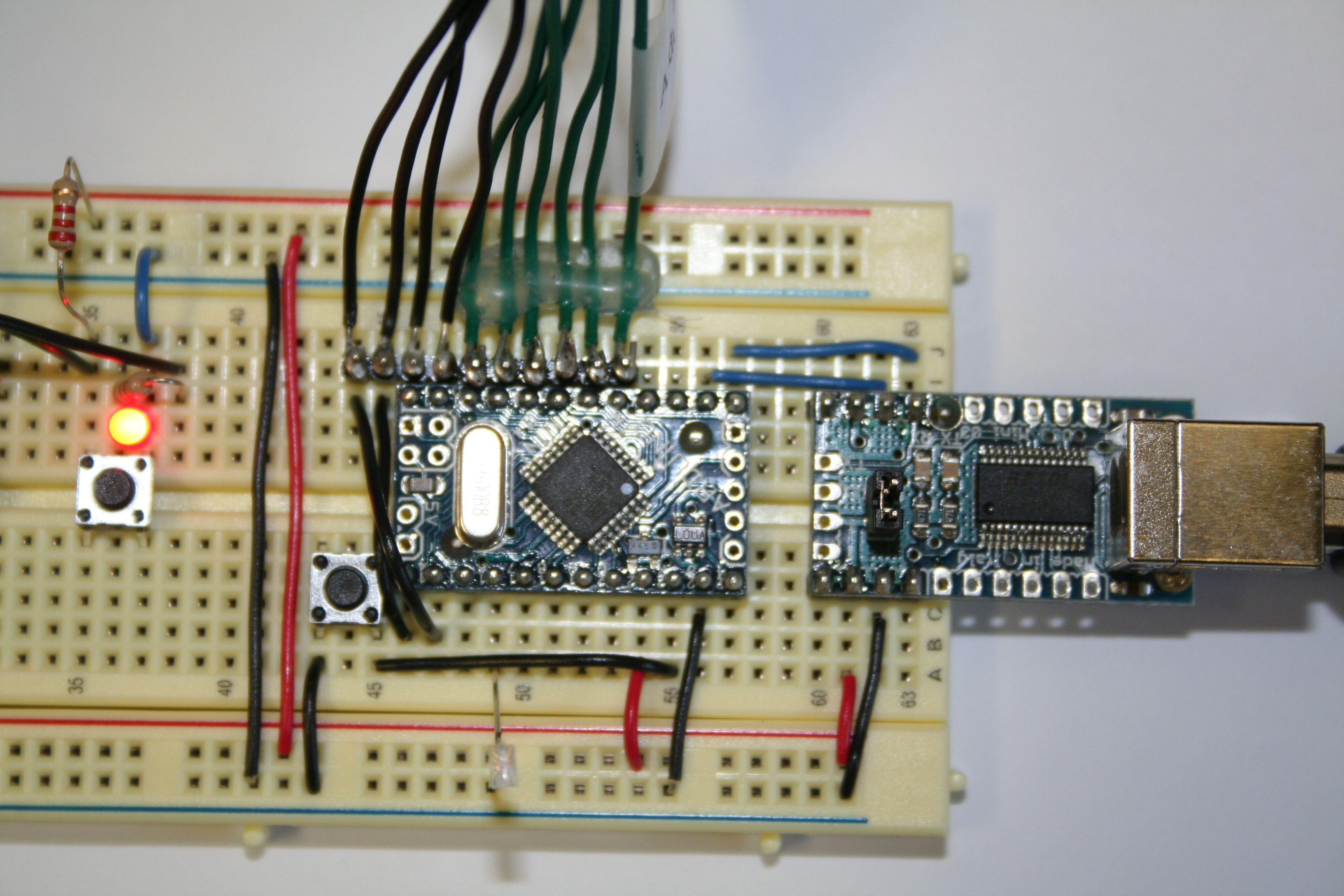
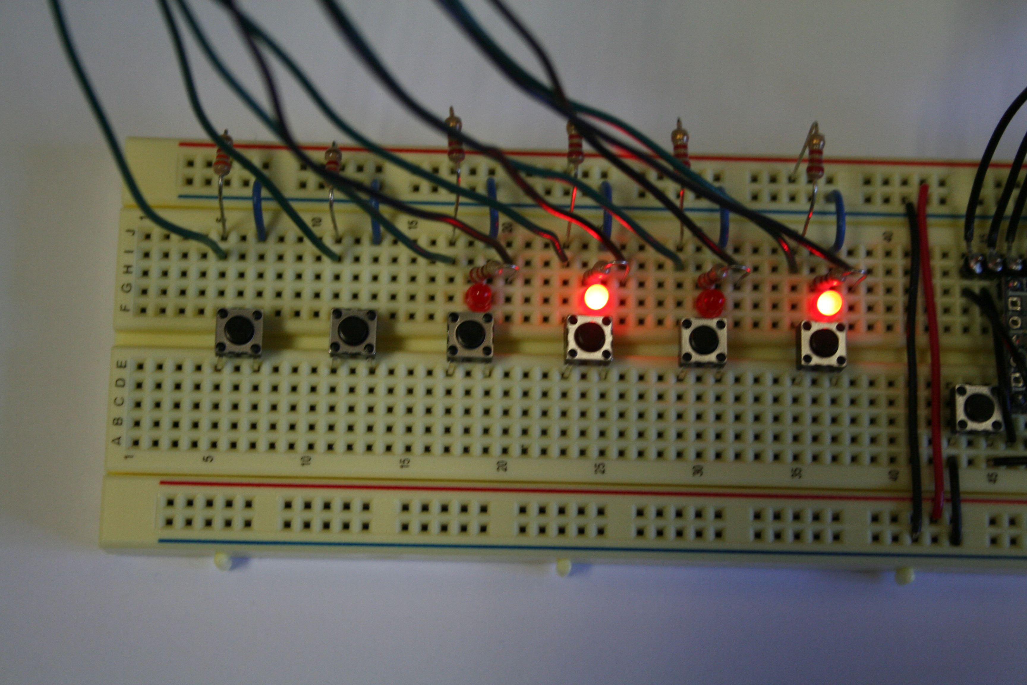
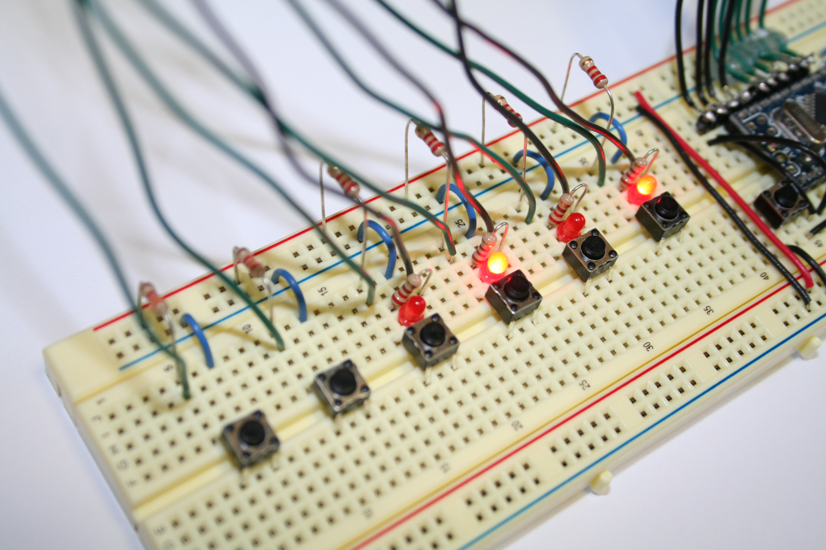
There are a variety of ways this can be wired up depending on the breadboard size and your aesthetic sense. The layout of your circuit is left as a fun exercise. Be sure "VERBOSE" is defined as "true" in the script and use the Arduino development environment's serial monitor to see that your prototype is functioning properly. A USB-powered breadboard prototype with an Arduino Mini is shown in these pictures:

The circuit can just barely fit on an Arduino Protoshield with a mini breadboard. Here are instructions for a Protoshield 4-bit maze layout. The result is shown in the pictures below.
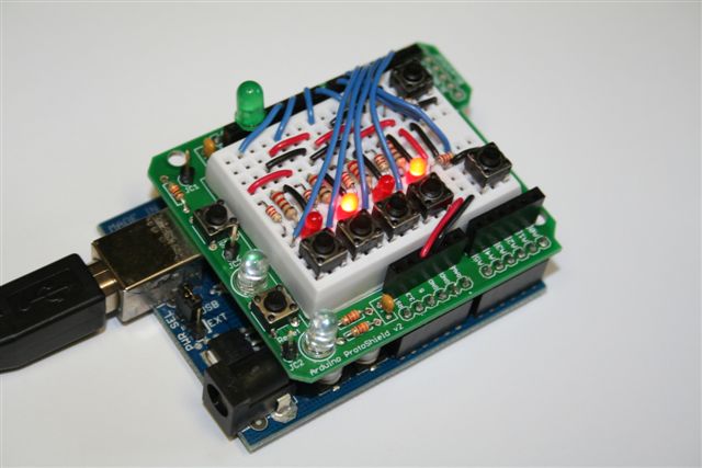
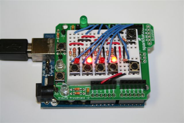
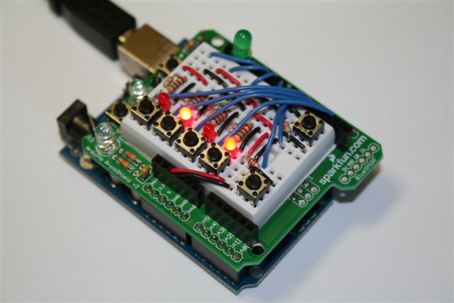
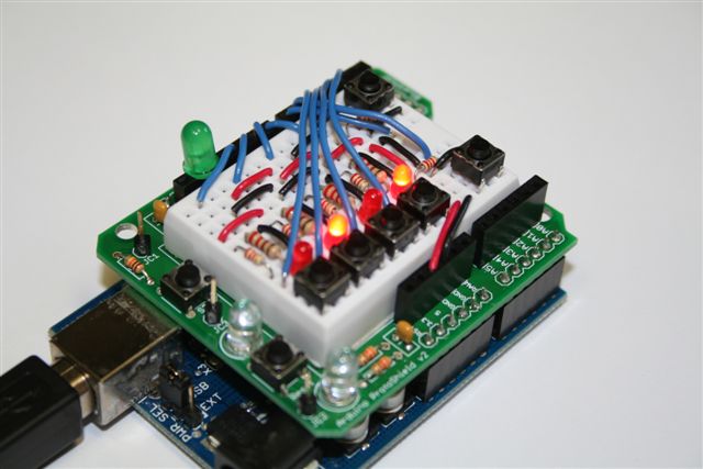
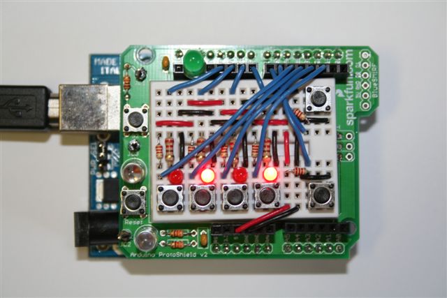
Note: Even straightening the pins of Sparkfun's pushbutton switches (Sparkfun COM-00097), they can sometimes pop out. If anyone knows of a .3"x.3" footprint tactile switch that is better suited for breadboard use, please let me know.
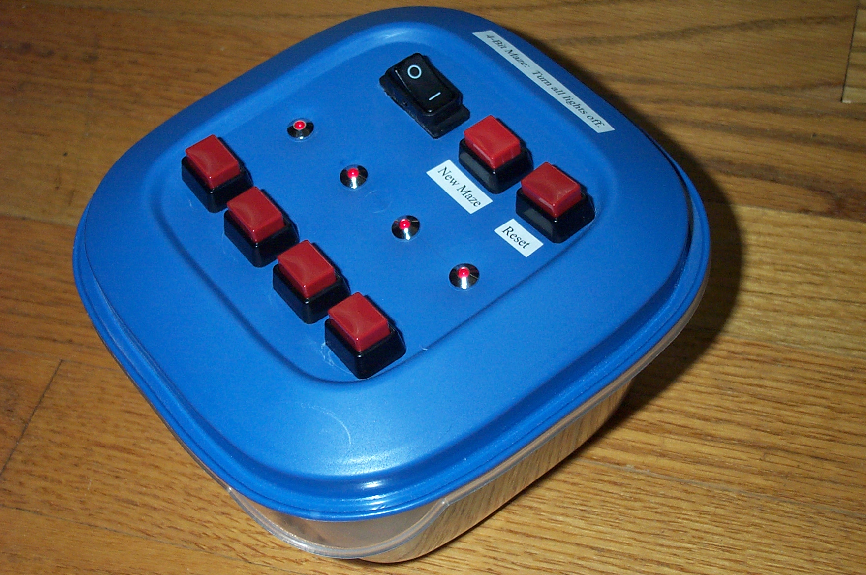
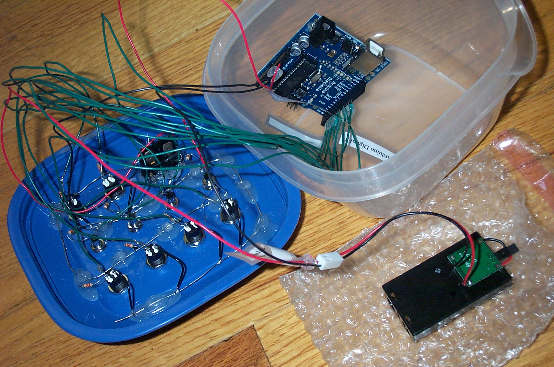
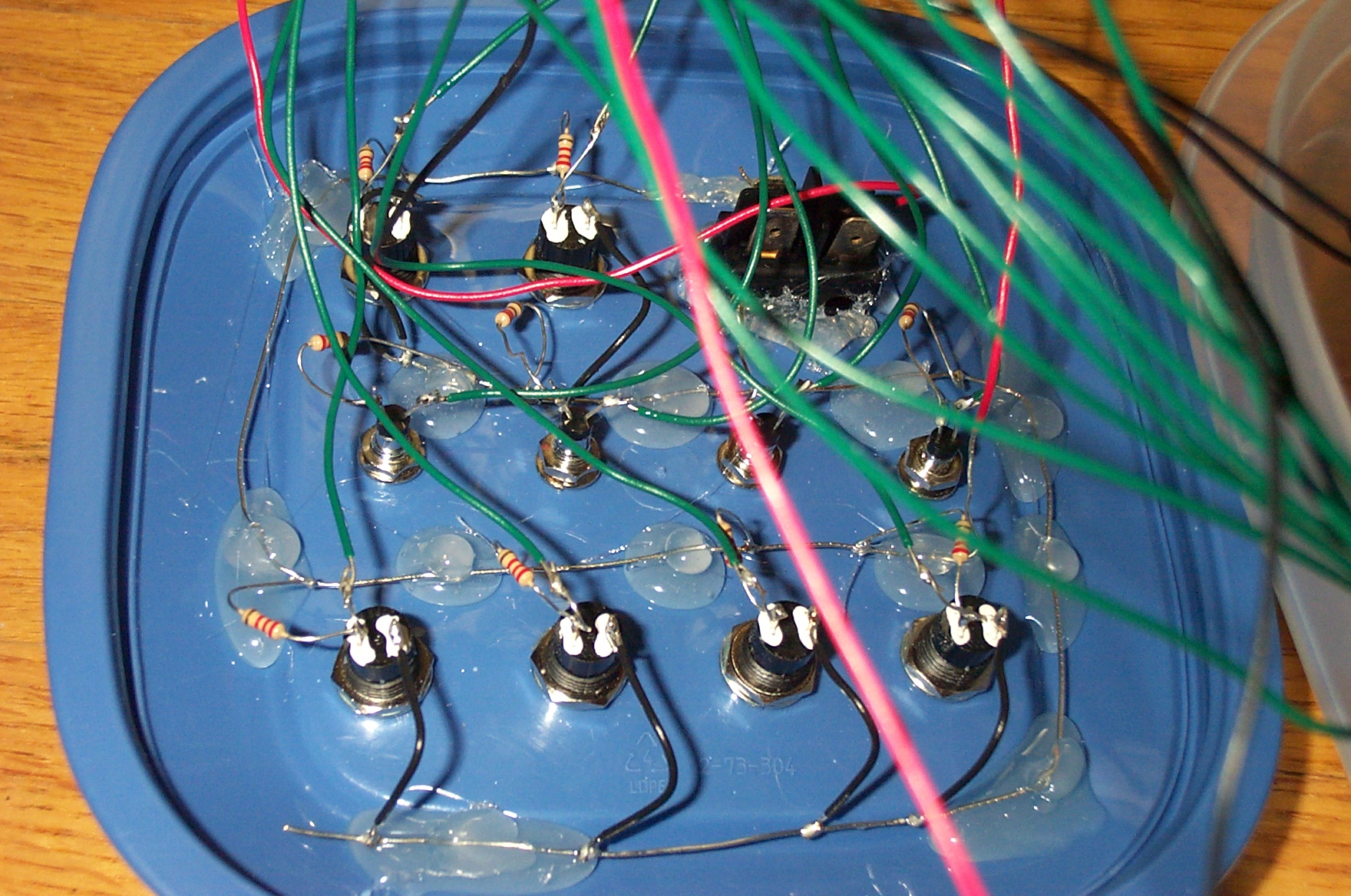
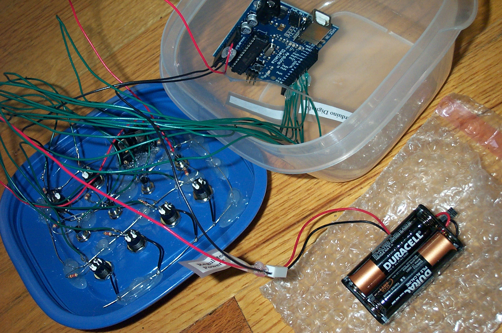
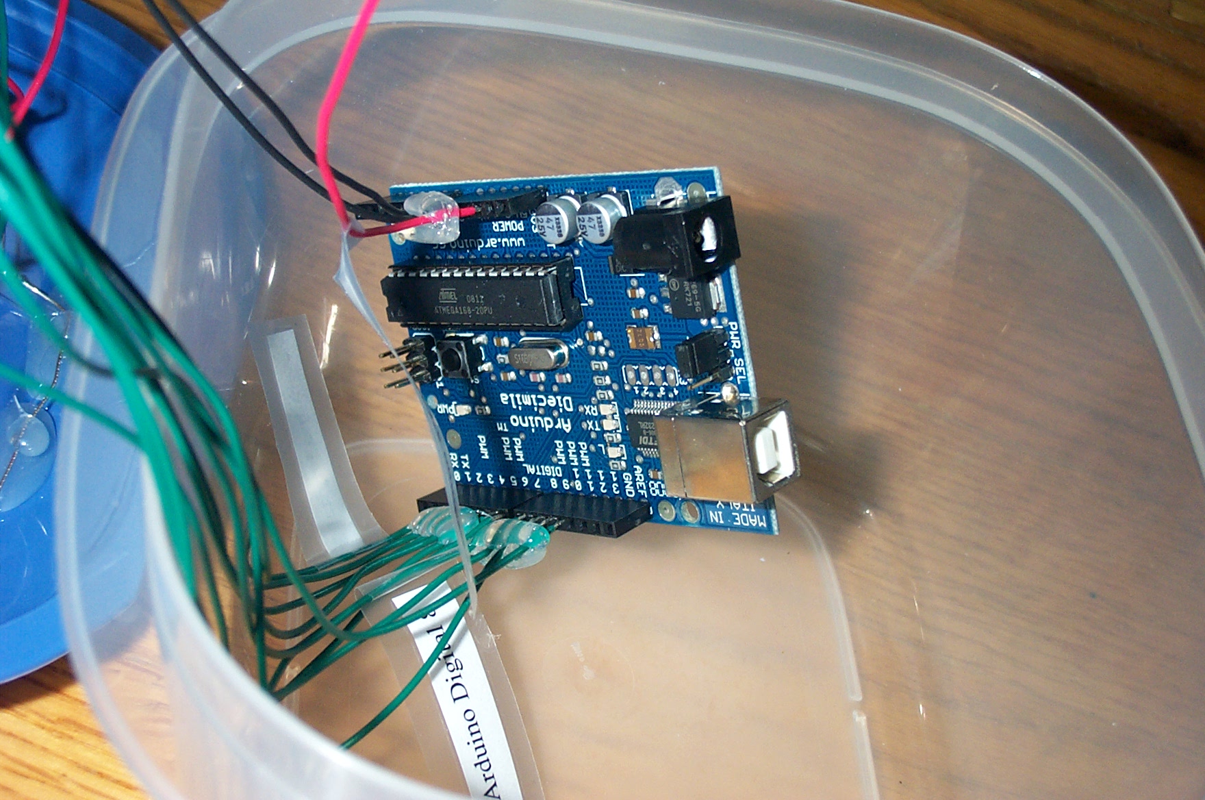
Shown in the pictures below is my "dead bug"-style prototype of the four-bit maze circuit. For this construction, one doesn't need a breadboard, and additionally needs:
An overview of the process:
The result is a beautiful, functional mess. :-)

Disclaimer: My only previous electronics experience is from my youth with Radio Shack electronics kit exercises and limited undergraduate prototyping with breadboards, PLAs, and very little soldering. Thus, I've likely made design decisions that would make a seasoned pro wince. My specialty as a computer scientist is artificial intelligence, and my electronics training is minimal.
If you have an alternative design, let me know! I may later post links to related work. In the meantime, enjoy the sketch, and have fun with some form of circuit implementation!
Last updated 4 August 2008
Todd Neller
![]()